PIAT: Part One

Anti-Tank, Custom builds, PIAT, Products, Weapons, WWII

Using CAD has started to become a bit of a habit… The PIAT was no exception!

I wanted to use a massive spring in this, even though there are more practical ways of firing a shell it’s true to the original and has some serious man-points attached!

Screen Shot 2015-08-25 at 18.38.15

This is actually my second design, my initial design was slightly different internally and used the direct power of the spring to drive the projectile. Although this worked in my initial experiments, once I made the piston captive (necessary to stop half a kilo of steel from smacking someone in the face) the ball barely fired. The redesign will use a CO2 shell or blank-firing mechanism depending on use._DSF5532

_DSF5534

The buttplate is 2mm folded steel, welded into place purely for aesthetic reasons, as the original was stamped steel. Once polished up that is how it will look.

Sight units next: foresight and rear sight are different shapes but much the same idea. I fitted them together before welding so that they would line up correctly.

_DSF5535

_DSF5537

With these two units complete, I could make the trigger mechanism. This is my version one, I have since then made some refinements that will make it smoother to use.

_DSF5540

One spring resets the second sear. You can see in this photograph that the spring pushes the sear up very high, this ended up being a problem as the force of the mainspring would make it almost impossible to actuate the mechanism. The next version fixes this by keeping the second sear at a usable height against the piston.

_DSF5542

All welded in place, ready to be cleaned up.

_DSF5545

Testing rig prior to making the piston captive. I also ended up making lightening cuts to the piston to improve travel speed. You can see the size of the spring in this shot, at one point I was unfortunate enough to be in the way of the piston when the sear slipped and it gave me a smart upper-cut to the chin. Fortunately it was only at half-cock otherwise I would have been in a pretty bad way!

_DSF5546

So, I’ll admit I have skipped a bit ahead here but the back end of the launcher was pretty well finished at this stage except for some adjustments to be made just before completion. Like the original, re-cocking is achieved by standing on the buttplate and lifting the rest of the launcher. I set to work on the fore-end that would hold the projectile.

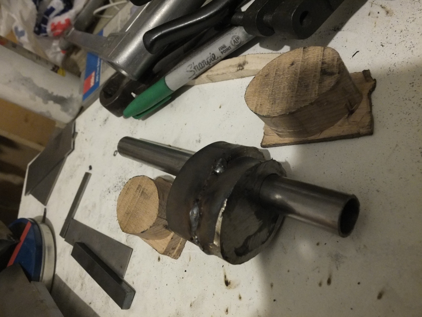
This is a spare piece of mild steel tube I had left over from a previous build. I marked out the cutout on the top and removed it with an angle grinder.

_DSF5852

I then cut out a steel disk for the back of the head, drilling the centre for the ‘spigot’ (the steel rod that in the real version would fire the explosive charge in the shell) to come out of. This could then be welded in place along with the collar that attaches the head to the body. Five screws distributed around the circumference hold it in place.

As well as the mainspring, at this point I added a smaller spring that sits around the spigot to absorb the shock of the piston finishing its travel. This spring just bounces freely off the back of the head.

As I said at the start, this is the point where testing became less successful. Without the weight of the piston carrying the tennis balls I was firing originally they only just left the barrel. As a result, the design is being modified to take CO2 grenades. In the longer run it will also be able to fire blanks for re-enactment purposes.


If you are interested in this build, have any questions or would like a build of your own, let me know! Our email is: enquiries.vintageairsoft@gmail.com or you can contact us through our Facebook page!

G43: Part One

Custom builds, G43/K43, Rifles, Weapons, WWII

_DSF5918 _DSF5919

As regular readers of this blog and the Facebook page will be aware, many of the projects begin with some intense design work and a lot of laser cuttings! I was particularly looking forward to getting these as it was my first venture into mass-preparing parts for hand folding.

I tend to run several components’ production in parallel so that i can be working on one as another cools, but the first job was assembling this little former:

_DSF5925

This shape allows me to very accurately bend the front sight hood by hand.

_DSF5927

_DSF5928

This done, I did much the same with the barrel band and drilled them so that the unit could be assembled with the sight post in the middle.

_DSF5932

_DSF5933

The one screw loosens and fits the whole unit. I may do some more work on the appearance of the foresight itself but it’s not bad as a first attempt!

Next was the front band, the part that ties the top and bottom of the stock together.

_DSF5935

Again I made formers, this time out of wood, for the strips of steel going around the woodwork. These were then viced with the plates that corresponded to them and welded in place. I rather conveniently had a piece of steel pipe exactly the same diameter as the barrel of the M14 I’m working from in order to assemble these parts.

_DSF5971 _DSF5972

Clean, polished and fitted to the gun for the first time. I must confess that even I was surprised at the first fitting with no modifications needed at all!

With the receiver came a lot more bending. Each panel was hand bent over a piece of 38mm steel tube.

_DSF5931

Once the curve was pretty close, the appropriate endcaps and features were welded in place, holding the exact curve needed.

_DSF5930

I then had to fit it to the gun:

_DSF5975

Clamped in place, ready to go! At this point my angle grinder gave out. Typical.
_DSF5977A quick trip to Screwfix later and I could get to work removing the receiver unit from the gun. I had hoped to keep this intact but it turned out to be integral to the gearbox housing so it had to go!

_DSF5978

Once the main part of the receiver was gone, I could trim away the remainder of the receiver that was in the way. At this point I had to make some adjustments to the stock in order to fit the disk at the back of the gun. A straight bit cut away the space needed and a small channel where there would be a curved lead in like the original G43.

_DSF5979

_DSF5982

Cut away stock, also trimmed down at the front for the top guard. I will need to make a filler piece for the lead in to the receiver as the stock was pretty hollow at this point to fit the gearbox in.

The last photograph shows the fit of the parts so far. I’m happy with the back two, but I will need to modify the rear sight and chamber to fit over the hop unit/barrel mount. I will be putting strips of steel down the edge of the receiver to help it fit absolutely spot on.

_DSF5983

So far this had been a really fun build, it’s nice to be able to focus on the cosmetics for a change!

If this post has inspired you to want a custom gun of your own, drop us a line on enquiries.vintageairsoft@gmail.com to discuss or find us on Facebook.

G43: Hitler’s Garand

Custom builds, G43/K43, History, Weapons, WWII

Firstly, apologies for not posting in an age, I’ve been too busy building and not doing enough writing!

The Farquhar-Hill, an experimental British semi-automatic rifle.

The Farquhar-Hill, an experimental British semi-automatic rifle.

Semi-automatic rifles were not a new technology by the Second World War, indeed they were available from the 1890s for those who really wanted to stay ahead of the curve: this not being all that long after the bolt-action/magazine combination was widely accepted. In spite of the seemingly obvious advantage of semi-automatic fire to the modern viewer, it took some time before it was widely adopted.

The 1907 Mondragon, a Mexican semi-automatic rifle. Interestingly Mexico was one of the first militaries to adopt this technology.

The 1907 Mondragon, a Mexican semi-automatic rifle. Interestingly Mexico was one of the first militaries to adopt this technology.

In the interwar years, most of the major nations experimented with semi-automatic rifles though only the US adopted it as their main rifle technology. That said they decided to sit out the first two years of the Second World War so had a bit more time to faff around.

The advent of the Second World War actually put back the adoption of semi-automatic rifles in Europe as there was a sudden need to re-arm without time for developing the new weapons. As a result, pretty well every nation went to war with the same rifles as they fought the Great War with.

Russian SVT-38

Russian SVT-38

On the Eastern Front, German forces generally made good headway against the Soviets, thanks mostly to their major superiority in the air and mobility. One of the few sticking points was where they came up against troops armed with the SVT40 and SVT38 semi-automatic rifles.

As a result, the Wehrmacht put out a tender to German manufacturers for a semi-automatic rifle:

  • No holes for tapping gas for the loading mechanism were to be bored into the barrel
  • The rifles were not to have any moving parts on the surface
  • In case the autoloading mechanism failed, a bolt action was to be included

The latter two make some sense even to modern eyes. The former was the result of paranoia that tapping gas for a reloading mechanism would sap the power of the bullet. The G41 used the ‘Bang’ system instead*. This system uses a ‘cup’ at the muzzle end to capture the blast and move the long operating piston. Sadly this system proved sensitive to dirt, hard to clean in the field and suffered from exposure to the corrosive chemicals used in primers of the era.

As a result of these problems among others, the G41 has earned a reputation of being possibly the most unreliable rifle of the era.

G41 (M), the particularly dreadful Mauser version of the G41.

G41 (M), the particularly dreadful Mauser version of the G41. The swollen fore-end of the barrel is the cup that captures the muzzle blast. If you take this off it is full of lots of small parts.

This was not good enough for the Wehrmacht who had the rifle redesigned, using the Tokarev system for inspiration.

The result was the G43, a far more effective rifle, but the Germans still weren’t quite happy! G/Gewehr meant ‘long rifle’. At only two centimetres longer than the Kar98k the Germans felt It was too short to be ‘gewehr’ so in time renamed it K43.

Left and right sides of the G43. The scope rail is on the side of the receiver above the trigger in the top image.

Left and right sides of the G43. The scope rail is on the side of the receiver above the trigger in the top image.

Beyond this the rifle stayed much the same for the duration of the war with mainly minor alterations. A scope rail was added and featured on most production rifles so that a Zf4 scope could be used, though this was only special issue.

9387045_1

G43 with ZF4 scope mounted.

Over the next month or so I’ll be converting an M14 into a G43 lookalike, as usual sharing the results here! If you would be interested in an M14 to G43 or G41 conversion let us know on the usual email address: enquiries.vintageairsoft@gmail.com. You can also ‘like’ our Facebook page for interesting articles, web pages and incremental developments


Fun facts!
  • Later in the war some last-ditch K43s were produced to run on the 8mm Kurtz intermediate round and use Stg magazines
  • The Zf4 was the ONLY scope used by the Wehrmacht in WWII on the G43
  • German soldiers were instructed to make semi-automatic rifles unusable if capture was imminent, as a result many examples are found with broken butt stocks

*named after Søren H. Bang, the mechanism’s inventor