M2 60mm Mortar: Complete

Area effect, Area-effect, Cold War, Complete builds, Custom builds, M2 60mm Mortar, Products, Weapons, WWII

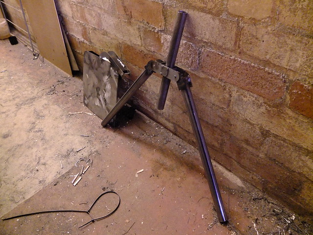
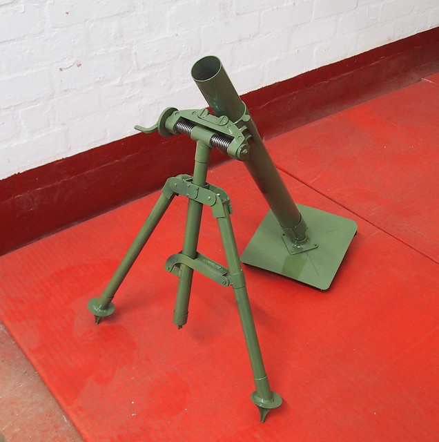
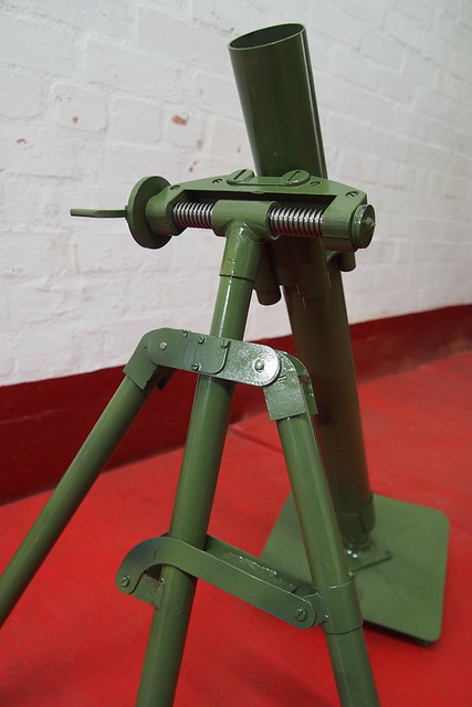
The mortar is finished, and what a beauty she is too, though I say so myself.

P1010094 copy

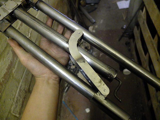
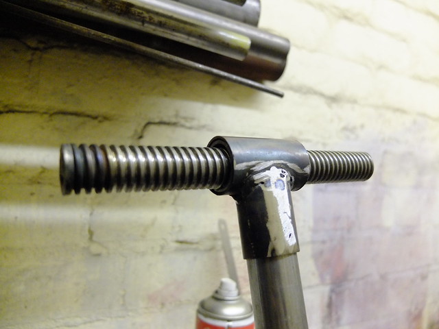
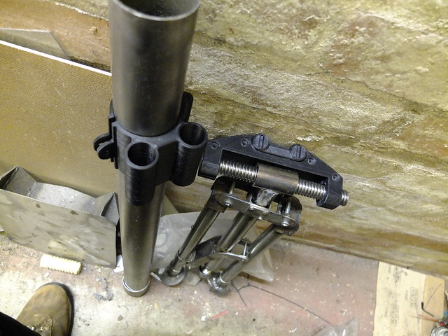
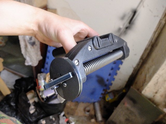
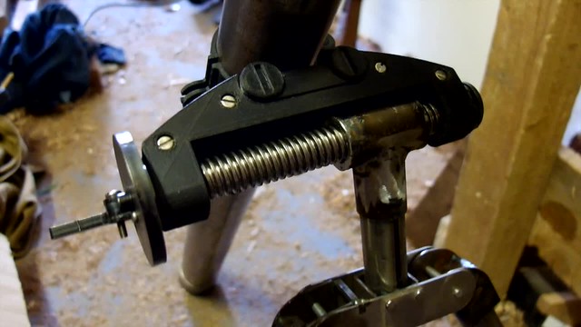
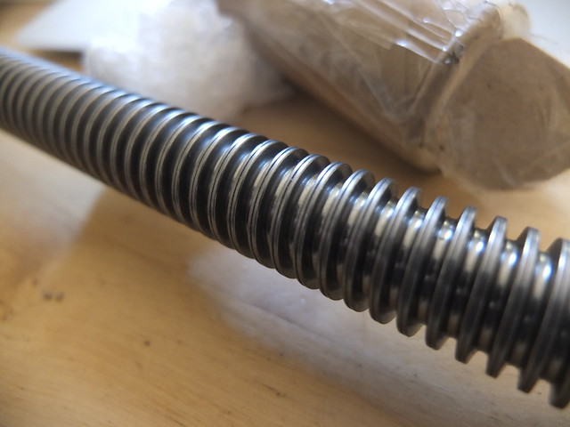
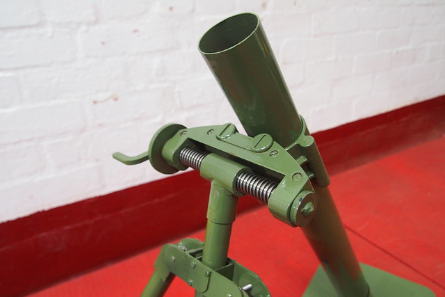
The adjustable windage is quite smooth, the folding handle giving adequate purchase and leverage.

P1010095 copy

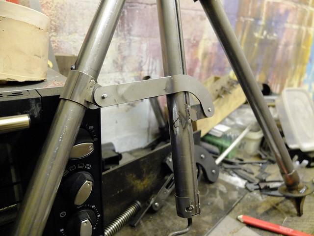
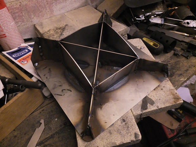
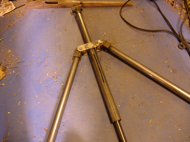
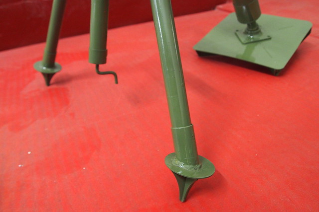
While the leg spreading system has its advantages, I can’t help but feel there are simpler designs that would have had the same result. Perhaps the reasoning is plainer with a live firing version.

P1010096 copy

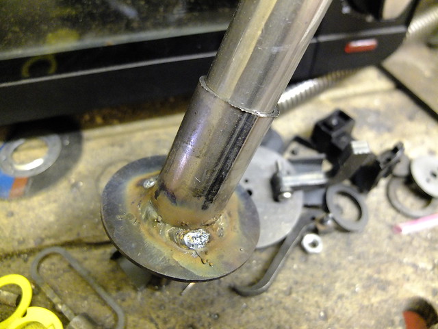
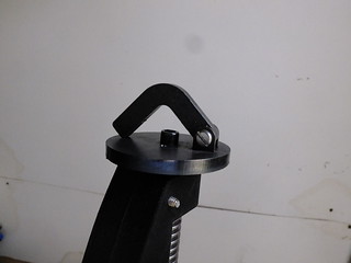
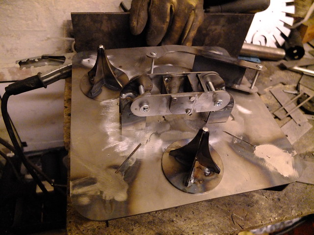
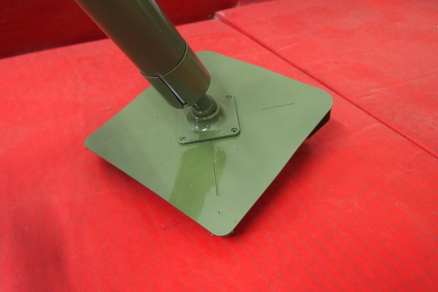
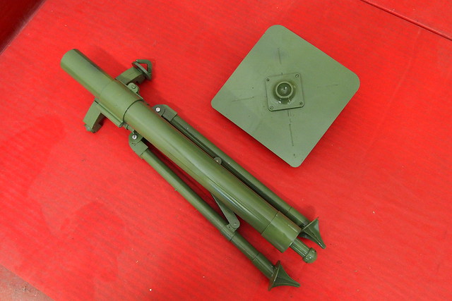
The baseplate has a 3D printed socket for the ball to slot into. On the original this is stamped into the plate design and features a lock, but here the ball is left free so that the barrel can be quickly upended and spent shells ejected.

P1010097 copy

The spikes on the bipod should keep it raised just high enough to give access to the elevation control in the centre.

P1010099 copy

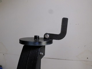
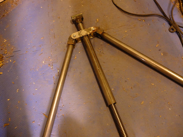
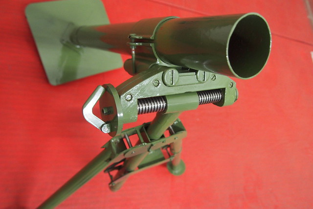
A top-down view, showing the windage lever in the stowed position.

P1010101 copy

Once packed away, this mortar isn’t actually too bad for portability. Considering the complexity and the precision you could achieve out to a respectable range on the original, you can see why modern light mortars are more closely related to this package than the T89 or SMBL 2″ families. While they may have portability and speed on their side, the ability to fine-tune fire for only a little extra weight and bulk certainly has its appeal.

P1010103


If you liked this project or have an idea of your own, drop us a line on enquiries.vintageairsoft@gmail.com to discuss. ‘Like’ our Facebook page or follow the blog to get regular updates on projects and interesting videos and articles.

You can find the build posts for this mortar here.

Don’t forget you can buy some of our complete products via Etsy. If you would like to commission a build like this, please drop us a line on the above email.


M2 60mm Mortar: Build 2

Area effect, Cold War, Custom builds, M2 60mm Mortar, Weapons, WWII

The first job of the next leg is to fit the leg limiter. This has two lugs on the centre column and on the left leg. Between this and the attachment at the head of the tripod it helps the user to keep the elevation adjustment vertical, even on sloped or bumpy ground.

_DSF9611

When deployed, the limiter sits pretty much horizontal. The collar it is attached to on the leg slides up and down, with a stop at the top of its travel to make it level out. In these two pictures you can also see the elevation adjustment handle. This piece of steel bar was bent and is screwed and pinned in position so that it can’t rotate without operating the elevation screw.

_DSF9626

The feet are welded onto sockets that fit over the bottom of the legs.

_DSF9627

And are in turn are spot welded onto the legs. These feet will allow the operator to dig the legs into the ground for stability when firing.

_DSF9631

The windage screw has a metal sheath, which I’ll be adjusting to be a nice, close fit. It will also have to have a tooth of some kind to work against the screw.

_DSF9628

With some rather happy timing, these 3D printed parts then arrived. Printed in ABS for strength, if they prove to not be up to the task I shall try casting them in aluminium. I suspect they’ll do beautifully though, these are very solid shapes.

_DSF9640

Roughly put in place, the mortar is really taking shape now. To finish off these parts, I need to fit a large screw to the barrel clamp and screw together the two halves of the windage unit. The windage screw also needs a little modifying to remain locked into the unit, rather than walking out either side.

_DSF9645

The two halves of the windage unit screwed together. This is a very rigid unit, as it needs to be to function. The screw thread is very stiff and it will need a little modification to work smoothly.

_DSF9652

With a little time on the lathe, I reduced the ends of the screw thread down so that they ran smoothly in their mountings. I also drilled and tapped each end for the stoppers that prevent it from leaving the windage control.

_DSF9653
The windage adjustment dial has a folding handle, like the original.
_DSF9655 _DSF9656

In place, it sits well and works quite smoothly. I think the barrel vise will need a little re-enforcing for use but it’s not bad even as is.
_DSF9770

A quick demo, it’s a bit awkward videoing and operating it at the same time but it’s easy to use.

M2 mortar windage
 

The last bits are the baseplate and baseplate ball, plus a fair bit of finishing. This thing will take some serious painting!

You can see the previous build post here.

If you are interested in the history of the M2, you can check out the introduction article here.

If you like this project or have an idea of your own, drop us a line on enquiries.vintageairsoft@gmail.com to discuss. ‘Like’ our Facebook page or follow the blog to get regular updates on projects and interesting videos and articles.

Don’t forget you can buy many of our complete products via Etsy.

M2 60mm Mortar: Build 1

Area-effect, Cold War, M2 60mm Mortar, Weapons, WWII

The project started with a good deal of research, finding pictures of all the component parts. From this I calculated dimensions and drew up plans.

The M2 is quite a bit more complicated than the SMBL 2″ used by the British. For my flat laser cut parts, I’m looking at around 3x as many pieces: plus a number of cast or printed parts.

Screen Shot 2017-06-19 at 15.08.39

The baseplate is the first component to be assembled. This heavy plate is designed to stick into the ground to control and direct the recoil.

_DSF9085

Then the feet for the bipod legs and the hinge parts, Although the M2 is complicated, it does fold down quite tidily, which means a lot of moving parts.

_DSF9124

With the legs in place, the mortar starts to take shape. The tube through the middle will have the elevation control going through it, at the top of it will be the T-piece where the windage adjustment will sit.

_DSF9159

The thread arrived, it is a 20mm trapezoidal threaded rod which should be coarse enough to allow quick adjustments to be made, but fine enough to allow for accurate fire adjustment.

_DSF9259

The elevation adjustment screw in place and the T-piece at the top of the column (where the windage screw will go). There is a slit in the back of the column in which a screw sits that locks the inner column into the outer and engages the screw thread.

_DSF9302

When the elevation is raised to maximum, you can just see the thread through the slot at the back, but this will effectively be hidden by the barrel.

_DSF9303


The next components will be the windage adjustment and endcaps. These are going to be 3D printed in ABS for strength and will also have the barrel clamp.


If you are interested in the history of the M2, you can check out the introduction article here.

If you like this project or have an idea of your own, drop us a line on enquiries.vintageairsoft@gmail.com to discuss. ‘Like’ our Facebook page or follow the blog to get regular updates on projects and interesting videos and articles.

Don’t forget you can buy our complete products via Etsy.

M2 60mm Mortar: Introduction

Area effect, Cold War, History, M2 60mm Mortar, Weapons, WWII

The M2 Mortar was a US light service mortar designed for close support by infantry at company level. These filled the gap between hand grenades/rifle grenades and the larger (81mm) M1 used at battalion level.

"Members_of_a_Negro_mortar_company_of_the_92nd_Division_pass_the_ammunition_and_heave_it_over_at_the_Germans_in_an_almos_-_NARA_-_535546

The 81mm mortar in use with a mortar company of the 92nd Division.

It has its origins, much like nearly every modern mortar, in the WWI-era Stokes design. It was smoothbore, drop-fired and used a bipod/baseplate system.

kt3h4nf24q-FILEID-1.35.43

Doughboys with the WWI Stokes mortar.

Light mortars of the inter-war/WWII period fell into two categories: The first were simple, tubes held firmly by the user when fired and aimed by direct line of sight (such as the British SMBL 2″ and Japanese T89). The latter were complex, with coarse thread screws or other systems to control elevation and windage for very accurate controlled fire.

usmortaritaly

The M2 fell into the latter category, with an attachment for a sight that could be used for both direct and indirect fire. As a result, it could be used accurately at close to its maximum range (nearly 2,000 yards).

M4-Mortar-Sight

The sight used for the M2.

Post-WWII, the M2 served in Korea and numerous Colonial conflicts with the French, finally in Vietnam. The Chinese also locally produced their own copy. It was eventually replaced in 1978 by the M224 which is still in service today and increased range capacity by about 1/3rd.


You can see some footage of the M2 in action here:

The Airsoft version currently being built will fire TAGs and moscarts, with a possibility of using TLSFX shells as well.